How to Choose the Right PN25 Butterfly Valve?
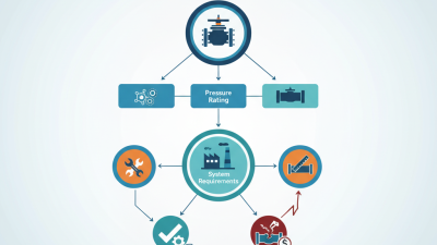
Choosing the right Pn25 Butterfly Valve begins with the operating conditions, not the catalog photograph. PN25 indicates a nominal pressure rating of 25 bar under defined temperature conditions. It does not mean the valve safely handles every fluid, temperature, or pressure combination. That detail matters.
Valve engineering author Robert W. Pritchard is often associated with a practical principle: “Valve selection must begin with the process, not the valve.” This idea guides the evaluation of body material, disc design, seat compound, shaft construction, and actuator type. A carbon-steel valve may suit treated water, while corrosive chemicals could demand stainless steel or a compatible lining. Small choices become expensive failures.
Check the line size carefully.
A DN100 pipeline may need a valve with a different flow coefficient than expected. Consider pressure drop, shut-off frequency, installation space, and maintenance access. Lug and wafer bodies also create different service requirements. If the valve sits near a pump, repeated cycling may expose weaknesses that static pressure calculations miss.
The Pn25 Butterfly Valve should also match the medium’s temperature and chemical behavior. EPDM, NBR, PTFE, and other seat materials do not perform equally. Certification, testing records, and traceable material documentation strengthen purchasing confidence. Yet specifications can still be incomplete. I have seen selections based on pressure class alone, followed by premature seat wear.
Use this guide to compare technical data with actual site conditions. The best choice is rarely the cheapest valve. It is the valve that remains predictable, serviceable, and safe after installation.
Define PN25: 25 bar Nominal Pressure at 20°C and Temperature Derating
PN25 means a nominal pressure rating of 25 bar, or 2.5 MPa, at 20°C. It is not a constant working pressure across every temperature. EN 593 and EN 12516-1 require pressure-temperature limits to be checked against the valve’s materials and construction. A steel-bodied butterfly valve may tolerate higher temperatures than a resilient-seated model. The seat often becomes the weak point.
Temperature changes matter quickly. At 20°C, a PN25 valve may be rated for 25 bar. At 120°C, its allowable pressure can fall considerably, depending on the body, disc, shaft, and seat. Never assume a simple percentage reduction. Check the manufacturer’s certified pressure-temperature table and the applicable design standard. ISO 5208 also provides leakage-testing procedures, but it does not replace pressure derating data. That distinction is often missed.
Field selection should begin with the actual operating case. Record pressure, temperature, fluid, cycling frequency, and possible pressure surges. A line carrying hot water at 18 bar may need more margin than its static pressure suggests. The 2023 International Energy Agency World Energy Outlook reports continuing growth in industrial electrification and heat-related demand, making hot-service valve applications more common. Yet, that report does not determine a valve rating. I would also verify flange drilling, face-to-face dimensions, and shutoff requirements. PN25 is a starting label, not a complete selection decision.
How to Choose the Right PN25 Butterfly Valve?
PN25 means a nominal pressure rating of 25 bar at 20°C. As operating temperature increases, the allowable pressure must be reduced according to the valve body, disc, seat, material standard, and applicable pressure-temperature table.
This reference profile shows a typical temperature-derating trend for a PN25 butterfly valve: 25 bar at 20°C, decreasing progressively at higher temperatures. Always confirm the certified pressure-temperature rating for the selected valve materials and service conditions before specification.
Match Body, Disc, and Seat Materials to Media and Corrosion Data
Choosing the right PN25 butterfly valve starts with process data, not the PN25 label. PN25 indicates a nominal pressure class under defined conditions. It does not guarantee safe service at every temperature. Record fluid composition, concentration, temperature, pressure, solids, and cycling. Then compare these values with material compatibility tables and test data. In field inspections, small chemistry changes often explain premature leakage. Water with chlorides is not always “just water.”
The body needs mechanical strength and corrosion resistance. Ductile iron may suit treated water, but aggressive chloride exposure can require coated steel or stainless steel. The disc contacts the fluid directly, so its alloy matters. Stainless steel is common, yet grade selection depends on chlorides, acids, and temperature. The seat controls shutoff. EPDM often handles water and mild chemicals. NBR may suit oils, but temperature limits still matter. PTFE resists many chemicals, though it can creep under load. Do not select from a general list. I sometimes see specifications copied from older projects. That is risky.
Tips: Build a compatibility matrix. Mark each material as suitable, conditional, or rejected. Check corrosion allowance, shaft material, and liner support. Request certificates and test conditions. If data is incomplete, choose a safer design or test the medium before ordering. A short pilot test can prevent a long shutdown. Leave room for doubt.
Size by DN, Kv, and a Target Flow Velocity of 1–3 m/s
Choosing a PN25 butterfly valve starts with the pipe’s DN, but DN alone is not enough. DN identifies the nominal connection size; it does not guarantee the best operating flow. On site, I verify the pipe bore, flange standard, medium, temperature, and available pressure drop. PN25 describes a nominal pressure class, not a promise of 25 bar at every temperature. That distinction is easy to miss.
Set a target velocity of 1–3 m/s for many water services. Lower velocities can reduce noise and erosion, while higher values may reduce valve size but increase pressure loss. Estimate flow with Q = v × πD²/4, using the actual internal diameter. For example, a 100 mm bore at 2 m/s carries about 56.5 m³/h. Check the arithmetic twice. A small diameter error changes the result sharply because diameter is squared.
Then compare the required Kv with the valve’s tested Kv data. Kv commonly means water flow in m³/h at a 1 bar pressure drop. Use Kv = Q/√(Δp/SG), including specific gravity for other liquids. Do not select only by matching DN. A partly open butterfly valve can create turbulence, noise, and unstable control. In practical commissioning, I leave adjustment range instead of operating near full closure. Confirm actuator torque, shutoff pressure, cavitation risk, and gasket compatibility in the technical documents. Calculations guide selection, but measured system behavior may still challenge them.
Choose Sealing Performance Through EN 12266-1 or ISO 5208 Classes
How to Choose the Right PN25 Butterfly Valve?
A PN25 rating indicates pressure capability, not complete sealing performance. For a reliable selection, examine the required leakage class under EN 12266-1 or ISO 5208. These standards define test methods, pressure conditions, and acceptable leakage limits for industrial valves. Their classes are not always directly interchangeable, so the purchase specification should name the exact standard and class.
Consider the operating medium, temperature, pressure, and cycling frequency. A valve handling clean water may perform differently from one carrying abrasive slurry or warm process fluid. Seat material matters greatly. Check whether the sealing arrangement suits the fluid and temperature range. Request factory test records showing shell strength and seat closure results. A clear report should identify the test pressure, duration, medium, and measured leakage.
Do not assume PN25 means zero leakage.
During inspection, check the disc edge, seat surface, shaft alignment, and flange connection. Even a well-tested valve can leak after poor installation or uneven bolt tightening. In my experience, selecting the tightest class is not always the best decision; it can increase cost without improving service life. A better approach matches the specified EN 12266-1 or ISO 5208 class with actual plant requirements. One detail is easy to miss: frequent cycling may gradually change seat performance, so maintenance records deserve the same attention as the initial certificate.
Verify EN 593, ISO 5752 Dimensions, and Actuator Torque Requirements
How to Choose the Right PN25 Butterfly Valve?
Choosing a PN25 butterfly valve requires more than checking the pressure label. A PN25 rating usually refers to nominal pressure at reference conditions. Temperature can reduce the allowable working pressure. I verify the valve’s pressure-temperature table before selecting materials. Do not rely on the nameplate alone. Check the body, disc, shaft, and seat specifications. Small errors matter. EN 593 provides important requirements for metallic butterfly valve design and performance. I also confirm testing records, material certificates, and documented quality controls from the supplier.
ISO 5752 dimensions deserve equal attention during installation planning. I compare the valve’s face-to-face length with the existing pipeline standard. Then I check flange compatibility, bolt-circle dimensions, and available clearance. A valve may meet EN 593 but still create installation problems. This is often missed. Measure the gap between flanges, especially in compact valve chambers. Never force the pipework to fit. Pipe stress can affect sealing and shaft operation. I have seen drawings look correct, while site measurements revealed a few critical millimeters missing.
Actuator torque must cover every operating condition, not only normal flow. Calculate breakaway, running, seating, and maximum differential-pressure torque. Include seat friction, media effects, temperature, and possible deposits. For automated service, compare the calculated torque with the actuator output throughout the full stroke. Keep margin, not guesswork. A small safety factor may be inadequate, but excessive torque can damage the seat or shaft. I sometimes find torque sheets based on clean water assumptions. That needs review when the process fluid is abrasive or sticky. Record the calculation beside the valve data sheet for future maintenance checks.
How to Choose the Right PN25 Butterfly Valve? - Verify EN 593, ISO 5752 Dimensions, and Actuator Torque Requirements
1. Core Selection and Standards Verification
| Verification Item |
Reference Standard or Requirement |
Recommended Selection Data |
What to Confirm Before Ordering |
| Valve type |
EN 593 |
Metallic butterfly valve for general-purpose pipeline service; wafer, lug, or double-flanged construction. |
Confirm the construction type, disc design, shaft arrangement, body material, and intended flow direction. |
| Nominal pressure |
PN designation used with European piping systems |
PN25, nominal pressure designation of 25 bar at the applicable reference temperature. |
Do not treat PN25 as a constant allowable working pressure at every temperature. Check the pressure-temperature rating for the body, disc, shaft, seat, and flange system. |
| Nominal size |
EN ISO 6708 and the selected piping system |
Typical range: DN50 to DN600 for industrial butterfly valve applications. |
Match the valve DN with the connected pipe inside diameter, flange bore, gasket type, and flow requirements. |
| Face-to-face length |
ISO 5752; commonly adopted through EN 558 |
Use the exact ISO 5752 series specified on the purchase order. The table below provides common Series 20 reference lengths. |
Confirm whether the valve is wafer, lug, or flanged and verify the drawing supplied for the selected pressure class and size. |
| Flange connection |
EN 1092-1 or the project-specified flange standard |
PN25 flange drilling and facing must match the connected pipe flanges. |
ISO 5752 defines face-to-face dimensions; it does not by itself define the complete flange drilling pattern or pressure-temperature rating. |
| Actuator mounting |
ISO 5211 |
Use an ISO 5211 mounting flange and stem interface compatible with the selected actuator. |
Confirm mounting flange size, stem square or key dimensions, maximum allowable stem torque, and available travel indication. |
| Leakage and testing |
EN 12266-1 and the project specification |
Define shell test, seat test, test fluid, test pressure, allowable leakage, and test duration in the inspection plan. |
Ensure the selected seat material and valve design are suitable for the specified shut-off class, temperature, and fluid. |
2. ISO 5752 Face-to-Face Reference Dimensions — Common Series 20 Values
| Nominal Size |
DN |
Reference Face-to-Face Length, L (mm) |
Typical Application Note |
Verification Status |
| 2 in | DN50 | 43 | Compact wafer or lug valve installation. | Verify against the selected Series 20 drawing |
| 2½ in | DN65 | 46 | Common process and utility pipeline size. | Verify against the selected Series 20 drawing |
| 3 in | DN80 | 46 | Suitable where a compact face-to-face arrangement is required. | Verify against the selected Series 20 drawing |
| 4 in | DN100 | 52 | Frequently used for water, HVAC, and general industrial service. | Verify against the selected Series 20 drawing |
| 5 in | DN125 | 56 | Confirm flange outside diameter and bolt-circle clearance. | Verify against the selected Series 20 drawing |
| 6 in | DN150 | 56 | Check disc clearance inside the pipe and adjacent fittings. | Verify against the selected Series 20 drawing |
| 8 in | DN200 | 60 | Confirm shaft orientation and actuator accessibility. | Verify against the selected Series 20 drawing |
| 10 in | DN250 | 68 | Check lifting, support, and installation space. | Verify against the selected Series 20 drawing |
| 12 in | DN300 | 78 | Review pressure drop and operating torque at the design flow. | Verify against the selected Series 20 drawing |
| 14 in | DN350 | 78 | Confirm flange alignment and actuator mounting clearance. | Verify against the selected Series 20 drawing |
| 16 in | DN400 | 102 | Check pipeline supports and valve lifting requirements. | Verify against the selected Series 20 drawing |
| 18 in | DN450 | 114 | Confirm site space, flange bolts, and maintenance access. | Verify against the selected Series 20 drawing |
| 20 in | DN500 | 127 | Verify structural loads and actuator output capability. | Verify against the selected Series 20 drawing |
| 24 in | DN600 | 154 | Check transportation, lifting, support, and full-disc clearance. | Verify against the selected Series 20 drawing |
Dimensional note: The listed dimensions are common ISO 5752 Series 20 reference values in millimetres. The certified valve drawing and the exact ISO 5752 series stated in the purchase specification remain the controlling documents. Flange drilling, valve overall height, disc diameter, stem height, and actuator envelope must be checked separately.
3. Materials and Service Compatibility
| Component |
Typical Material Options |
Selection Considerations |
Required Confirmation |
| Body |
Ductile iron, carbon steel, stainless steel, or other specified metallic material. |
Must satisfy the PN25 pressure-temperature rating and corrosion requirements. |
Confirm material grade, casting or forging standard, wall thickness, coating, and pressure rating. |
| Disc |
Ductile iron, stainless steel, duplex stainless steel, or another compatible alloy. |
Consider corrosion, erosion, cavitation, solids content, and fluid velocity. |
Confirm disc material, surface finish, balancing, and clearance from the pipe bore. |
| Shaft |
Stainless steel or a higher-alloy material for corrosive service. |
Must withstand operating torque, pressure loads, corrosion, and repeated cycling. |
Confirm shaft diameter, material, one-piece or two-piece construction, and allowable torque. |
| Seat and liner |
EPDM, NBR, FKM, PTFE, or metal seat, depending on service. |
Temperature, chemical compatibility, permeability, abrasion, and shut-off requirements are decisive. |
Confirm continuous temperature, peak temperature, fluid composition, leakage class, and cycle frequency. |
| Gaskets |
Material selected for the fluid, temperature, flange facing, and pressure class. |
Incorrect gasket compression or material compatibility can cause leakage even when the valve is correctly rated. |
Confirm gasket dimensions, material, thickness, and installation torque. |
4. Actuator Torque Requirement Example
| Torque Component |
Illustrative Design Value |
Unit |
Engineering Meaning |
| Seat or breakaway torque |
1,800 |
N·m |
Torque required to move the disc out of the closed seating position under the specified service conditions. |
| Disc and hydrodynamic torque |
900 |
N·m |
Torque caused by disc geometry, differential pressure, flow velocity, and fluid properties. |
| Bearing, packing, and mechanical friction torque |
350 |
N·m |
Resistance from shaft bearings, packing, seals, and internal mechanical friction. |
| Calculated running torque |
3,050 |
N·m |
1,800 + 900 + 350. |
| Recommended service factor |
1.30 |
Factor |
Illustrative allowance for variation, ageing, temperature, and operating uncertainty; the project specification may require a different factor. |
| Minimum design actuator torque |
3,965 |
N·m |
3,050 × 1.30. Select an actuator with a certified output torque at least equal to this requirement throughout the complete travel. |
| Illustrative actuator selection target |
≥ 4,000 |
N·m |
Indicative rounded selection only; the actuator torque curve, not the nominal catalogue maximum alone, must be checked. |
Torque note: There is no universal actuator torque value for every PN25 butterfly valve. Final sizing must use the valve manufacturer’s certified torque data at the maximum differential pressure, minimum and maximum temperature, operating medium, seat type, cycling frequency, and required safety factor. For fail-safe actuators, size the spring-return torque separately for both opening and closing directions.
5. Final Purchase Specification Checklist
| Checklist Item |
Required Data to Record |
Acceptance Check |
| Valve identification |
Butterfly valve, DN, PN25, wafer/lug/flanged configuration, flow direction. |
Must match the piping and process datasheet. |
| Standards |
EN 593, ISO 5752 series, EN 1092-1 flange system, ISO 5211 actuator interface, and EN 12266-1 testing where specified. |
Standards and editions must be stated in the quotation and inspection documents. |
| Dimensions |
Face-to-face length, flange drilling, bore, disc clearance, stem height, and overall actuator envelope. |
Certified general arrangement drawing must fit the existing installation. |
| Pressure and temperature |
Design pressure, maximum differential pressure, operating temperature, test pressure, and pressure-temperature derating. |
All wetted and pressure-retaining components must be rated for the complete design envelope. |
| Materials |
Body, disc, shaft, seat, liner, fasteners, coatings, and gasket materials. |
Materials must be compatible with the fluid and environmental conditions. |
| Actuator |
Required torque curve, operating time, control signal, fail position, ISO 5211 mounting, limit switches, and accessories. |
Available actuator torque must exceed the certified valve torque at every required operating condition. |
| Inspection documents |
Material certificates, pressure-test records, dimensional inspection, coating records, and actuator test records. |
Documentation must be supplied according to the project quality plan. |