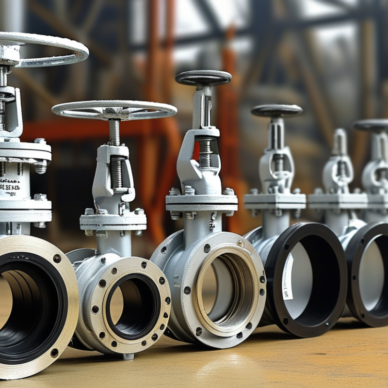
Choosing a Double Flange Butterfly Valve in 2026 requires more than comparing prices and catalog photographs. The correct valve must match the pipeline’s pressure rating, media, temperature, flange dimensions, and operating frequency. A valve installed in a chilled-water line faces different demands from one handling abrasive slurry. Small differences matter.
This guide explains the practical checks used by experienced engineers and maintenance teams. It examines valve-body materials, liner selection, disc design, shaft sealing, and actuator sizing. It also considers manual, electric, and pneumatic operation. A correctly selected actuator should overcome breakaway torque, not merely the valve’s average running torque. That detail is often missed.
Field experience shows that many failures begin before installation. Incorrect flange alignment can damage the seat. Poor storage may expose sealing surfaces to dust or moisture. Some product sheets also provide incomplete torque data. That creates uncertainty. Buyers should request pressure-test records, material certificates, dimensional drawings, and clear warranty terms from reputable manufacturers.
There is no universal best valve. A resilient-seated model may suit clean water, while a metal-seated design may better tolerate higher temperatures or demanding service. However, every recommendation needs verification against the actual process conditions. This article will help readers compare options logically, identify hidden risks, and build a reliable specification for 2026 projects. Expect practical guidance, but allow room for review. Real systems are rarely as simple as the original specification.
A double flange butterfly valve controls flow by rotating a circular disc inside the pipeline. The disc turns around a central shaft, usually through 90 degrees. When fully open, it aligns with the flowing medium and creates limited resistance. When closed, it turns across the passage and presses against a sealing surface. That is its role.
The double flange design connects directly between two pipe flanges. Its body supports the pipeline more firmly than some lighter wafer arrangements, especially in larger diameters. During site inspections, engineers should check bolt alignment, gasket condition, and shaft movement. A small installation error can damage the seal before operation begins. The valve may regulate flow, but it is usually more reliable for isolation than precise throttling.
Choosing one in 2026 requires more than matching pipe size. Confirm the medium, pressure, temperature, flow direction, and required operating frequency. Water service may suit a resilient seat, while abrasive or chemically active media require different disc and seat materials. Calculate actuator torque with a safety margin, including possible deposits on the disc. Standards and test records improve reliability, but paperwork cannot replace a real inspection. This is where selection often becomes imperfect: operating data may be incomplete, and conservative assumptions can increase cost unnecessarily. A careful review of field conditions remains essential.
Choosing a double flange butterfly valve in 2026 starts with the process fluid, not the catalog diameter. Water, seawater, acids, solvents, and slurries attack different materials. For clean water, ductile iron with an EPDM seat may be practical. Seawater usually demands stronger corrosion control, such as coated bodies and suitable stainless trim. Do not assume stainless steel solves every problem. Chlorides can still cause pitting.
Check pressure, temperature, and velocity together. A seat rated for 120°C may lose elasticity under pressure cycling. EPDM suits many water services but performs poorly with oils; NBR handles oils better, yet heat limits matter. PTFE tolerates many aggressive chemicals, but its sealing behavior and cost need review. For abrasive slurry, lining hardness and shaft protection may matter more than body metal. Ask for pressure-temperature charts, material certificates, and test records. Standards such as EN 593 or API 609 can guide verification, but project specifications remain decisive.
In field reviews, I have seen valves selected from fluid names alone. That shortcut failed when concentration and cleaning chemicals changed. Record the actual media concentration, peak temperature, shutoff pressure, and corrosion allowance. Check flange drilling, face dimensions, actuator torque, and isolation requirements before ordering. A valve can fit perfectly and still fail early. I would challenge uncertain data instead of filling gaps with assumptions. That small pause often exposes the real material risk.
Choosing a double flange butterfly valve in 2026 starts with the pipeline, not the catalog. Measure the actual line, medium, pressure, temperature, and flow direction. A DN150 valve is not automatically correct for a DN150 pipe if flange faces or lining reduce the bore. Select size from required flow and acceptable pressure loss. Oversizing can cause poor control, while undersizing raises velocity and wear. In field inspections, I compare drawings with the installed pipe. Measure twice.
Disc design should match the service. A concentric disc suits many water duties and offers simple, economical operation. Eccentric designs can reduce seat rubbing during opening, helping larger or demanding lines. Consider shaft arrangement, disc clearance, torque, and downstream equipment. A disc that swings into a nearby elbow may create trouble. Do not judge by pressure rating alone. Request torque data across the full operating range.
Seat selection depends on the medium and temperature. Resilient seats often suit clean water, but chemicals, abrasive solids, or heat may require other materials. Check compatibility charts and confirm shutoff expectations under real conditions. Flange standard is equally critical. Match drilling, bolt circle, face type, gasket arrangement, and pressure class. In 2026, verify the latest applicable edition of ASME, EN, JIS, or the project standard. Never assume similar DN or NPS dimensions will mate. I once trusted a familiar drawing and missed a facing detail; the valve fit on paper, not on site. Have the supplier verify dimensions, materials, testing, and certification before release.
| Selection Dimension | Typical Options | When to Select It | Key Technical Check | Practical Recommendation |
|---|---|---|---|---|
| 1. Valve Size and Flow Capacity | ||||
| Nominal size | DN50–DN600 Approximately NPS 2–NPS 24 |
Select the valve size to match the connected pipe and the required flow capacity. | Confirm the pipe outside diameter, internal diameter, flange drilling, face-to-face dimension, and available installation space. | Do not select a valve only by matching the pipe size. Check the required flow coefficient, pressure loss, and operating range. |
| Flow velocity | Application-dependent | Suitable sizing depends on the fluid, solids content, temperature, pressure, and allowable pressure drop. | Oversizing may cause poor control at low opening angles; undersizing may create excessive velocity, noise, erosion, or pressure loss. | For throttling service, select a valve that normally operates in a stable mid-range rather than remaining almost closed. |
| Pressure rating | PN6, PN10, PN16, PN25, PN40 Class 150 or other specified ratings |
Choose a rating equal to or greater than the maximum design pressure and temperature of the system. | Pressure capability is affected by body material, seat material, temperature, flange rating, and the manufacturer’s pressure-temperature table. | Use the lowest applicable rating among the valve, seat, flange, bolts, and connected piping system. |
| 2. Disc Design and Operating Duty | ||||
| Concentric disc | Disc and stem are centered on the pipe axis. | General isolation and moderate-duty water, air, and compatible utility applications. | Usually provides a compact design and economical maintenance, but seat friction and wear can increase at higher pressure or temperature. | Use for straightforward on/off service where the pressure, temperature, and cycle requirements remain within the seat limits. |
| Double-eccentric disc | Stem is offset from the disc center and, typically, from the pipe centerline. | Higher-pressure water systems, frequent operation, larger sizes, and applications requiring reduced seat rubbing. | The offset reduces contact between the disc and seat during opening, helping lower operating torque and seat wear. | Often preferred when service is more demanding than standard concentric isolation but does not require a metal-seated triple-offset design. |
| Triple-offset disc | Three geometric offsets with a cam-like, generally metal-seated sealing arrangement. | High-temperature service, steam, hot gas, hydrocarbons, and applications requiring fire-safe or bubble-tight performance when properly specified. | Check allowable leakage class, fire-test requirements, thermal expansion, minimum operating torque, and material compatibility. | Use only when the application justifies the additional cost and engineering requirements; it is not automatically the best choice for ordinary water service. |
| 3. Seat Material and Fluid Compatibility | ||||
| EPDM seat | Common for water, treated water, and many dilute aqueous services. | Use when resistance to hot water, weathering, and ozone is important and the fluid is compatible. | Generally unsuitable for many oils, fuels, and hydrocarbon-based fluids. Confirm the temperature range from the valve data sheet. | A common starting point for municipal and industrial water, but verify disinfectant, chemical, and temperature exposure. |
| NBR seat | Common for oils, fuels, and selected hydrocarbon-related services. | Use when oil resistance is more important than maximum hot-water or ozone resistance. | Compatibility varies with aromatic content, additives, temperature, and fluid concentration. | Confirm the exact fluid composition before selection; do not substitute NBR for EPDM without a compatibility review. |
| PTFE or reinforced PTFE seat | Used for selected aggressive chemicals and higher-temperature applications. | Choose when chemical resistance and low friction are required. | Check cold flow, pressure rating, thermal cycling, permeation, and compatibility with the specific chemical. | Suitable for specialized service only after reviewing the complete chemical concentration and temperature profile. |
| Metal seat | Common in triple-offset designs for high-temperature or severe-duty service. | Use for high temperature, abrasive service, fire-safe designs, or applications where elastomers are unsuitable. | Metal-seated valves may have a specified leakage rate rather than the same shutoff behavior as a resilient-seated valve. | Specify the required leakage class and surface materials instead of assuming every metal-seated valve provides zero leakage. |
| 4. Flange Standard and Installation | ||||
| ASME flange systems | ASME B16.5 for many smaller nominal sizes and ASME B16.47 for larger flanges. | Use for piping designed to ASME dimensional and pressure-class requirements. | Match NPS size, pressure class, flange outside diameter, bolt circle, number of bolts, bolt-hole diameter, and raised-face details. | Do not combine a Class 150 valve with a different flange drilling pattern without confirming an approved connection arrangement. |
| EN flange systems | EN 1092-1, commonly PN10, PN16, PN25, or PN40. | Use for piping designed around European nominal diameter and PN pressure designations. | Confirm DN, PN rating, flange type, bolt circle, bolt-hole size, and face-to-face dimensions. | PN16 and Class 150 are not automatically interchangeable; compare the complete dimensional and pressure requirements. |
| JIS flange systems | JIS B 2239 pressure and dimensional series, where specified by the piping system. | Use for equipment and piping designed to Japanese Industrial Standard flange dimensions. | Check the relevant nominal pressure series, drilling pattern, gasket dimensions, and bolt requirements. | Verify the standard directly from the existing pipe flange; nominal size labels alone do not ensure interchangeability. |
| 5. Materials, Actuation, and Verification | ||||
| Body and disc material | Ductile iron, carbon steel, stainless steel, or other specified alloys. | Select according to pressure, temperature, corrosion, erosion, external environment, and fluid cleanliness. | Check corrosion allowance, coating or lining, chloride exposure, galvanic compatibility, and material certificates when required. | For corrosive or hygienic service, evaluate the complete wetted material set rather than selecting only a stainless-steel body. |
| Actuator type | Manual gearbox, electric actuator, pneumatic actuator, or hydraulic actuator. | Manual operation may suit infrequent isolation; powered actuation is preferred for remote, automated, or high-cycle operation. | Actuator sizing must include maximum shaft torque, seat breakaway torque, dynamic torque, safety factor, and fail position. | For safety-critical systems, specify open/close indication, limit switches, position feedback, emergency operation, and the required fail-safe action. |
| Final documentation | Data sheet, dimensional drawing, pressure-temperature chart, material list, test report, and installation instructions. | Required before purchase approval and installation. | Confirm the exact valve size, rating, disc design, seat, flange standard, face-to-face length, flow direction, test standard, and actuator details. | Approve the valve only after all interfaces and operating conditions have been checked against the piping specification. |

How to Choose a Double Flange Butterfly Valve in 2026?
Actuation choice should follow the operating task, not just pipe size. Manual gear operators suit infrequent isolation and provide direct, dependable control. Pneumatic actuators respond quickly in process lines, but they need clean, stable air pressure. Electric actuators fit remote operation where compressed air is unavailable. They also simplify scheduled automation. Check closing torque carefully. High-temperature media, pressure changes, and aging seats can increase resistance. I have seen undersized actuators stall during commissioning. That assumption can be costly.
Control features matter when the valve regulates flow. On-off service may need only open and closed limit switches. Modulating service requires accurate positioning, suitable feedback, and a compatible control signal. Consider local controls, emergency operation, enclosure protection, and fail-safe behavior. A valve that closes during power loss may protect equipment, but it may also interrupt cooling. Review the actual process response. Small details matter.
Installation requirements are often underestimated. Confirm the flange standard, face-to-face dimension, pressure class, and available actuator clearance. Keep the disc clear of nearby pipe welds and internal obstructions. Align the flanges before tightening bolts in a cross pattern. Do not use the valve to correct poor pipe alignment. It may work temporarily. It can also create uneven seat loading. Before service, operate the valve through its full stroke and verify feedback signals at the control panel. Record torque, travel, and any unusual noise for future inspection.
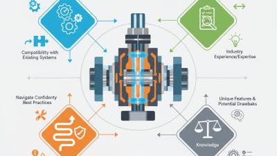
Comparison of actuation methods, control features, and installation requirements
The chart uses a practical engineering score from 1 to 5, where 5 indicates stronger suitability for the listed requirement. Manual gear operators are simple and easy to install, electric actuators support automation and precise positioning, while pneumatic actuators provide fast cycling and convenient fail-safe configurations when instrument air is available. Final selection should also verify valve torque, pressure class, flange standard, media compatibility, ambient conditions, and available utilities.
Choosing a double flange butterfly valve in 2026 requires more than matching pipe diameter. Verify EN 593, API 609, or the applicable national standard. Check pressure class, face-to-face dimensions, flange drilling, and tested temperature limits. ISO 5752 dimensions can prevent a costly installation mismatch. Request material certificates, pressure-test records, and traceability for the body, disc, stem, and seat. ISO 9001 helps, but it does not prove every valve performs correctly.
Maintenance needs deserve equal attention. Ask for seat replacement procedures, stem sealing details, actuator access, and spare-part availability. A valve hidden behind insulation is not maintenance-friendly. The NACE IMPACT study estimated global corrosion costs near US$2.5 trillion annually, or about 3.4% of global GDP. That figure is not a valve forecast, but it shows why coating, material selection, and water chemistry matter. I would also inspect installed valves after the first operating cycle. Early assumptions can be wrong.
Compare total cost, not only purchase price. The U.S. Department of Energy’s Operations and Maintenance Best Practices guide reports potential energy savings of 5–20% through effective maintenance. For powered actuators, include electricity, control-air demand, calibration, downtime, disposal, and emergency freight. Request a five-year cost model from each supplier. Include failure-response times. Supplier audits, batch testing, and documented nonconformance handling reveal more than polished brochures. Cheap can become expensive. Sometimes, even a well-specified valve fails because the application data was incomplete.