

What Is a Dismantling Joint and How Does It Work? — Maintenance Criteria: Torque Checks, Corrosion Control, and Safe Disassembly
| Maintenance Dimension | Inspection or Work Item | Recommended Method | Acceptance Criteria | Action if Non-Conforming | Typical Interval |
|---|---|---|---|---|---|
| 1. Functional Overview and Operating Principle | |||||
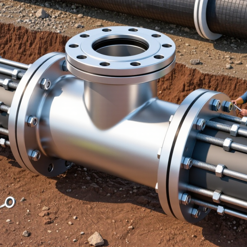
| Joint function | Axial adjustment and dismantling clearance | Verify that the telescopic or flanged joint provides controlled axial movement without overstressing the connected pipe, valve, or flange. | Movement is within the design adjustment range; no binding, uncontrolled sliding, or visible distortion is present. | Isolate the line and inspect tie rods, flange faces, seals, and pipe supports before returning the joint to service. | At commissioning and during major maintenance |
| Load transfer | Tie rods, bolts, nuts, and washers | Confirm that the restraint hardware transfers axial thrust and maintains flange alignment while the joint is pressurized. | Hardware is complete, correctly positioned, compatible with the design, and free from severe deformation or thread damage. | Replace damaged or missing hardware with components of the specified size, material, strength class, and coating. | Every scheduled inspection |
| Sealing | Gasket or elastomer seal condition | Inspect for leakage, extrusion, cracking, hardening, flattening, or chemical attack. Check that the seal remains seated. | No active leakage, abnormal seal extrusion, circumferential damage, or loss of elasticity is observed. | Depressurize safely and replace the seal; do not attempt to stop leakage by uncontrolled bolt tightening. | Visual inspection during operation; detailed check annually |
| 2. Torque Checks and Fastener Control | |||||
| Torque verification | Initial and in-service bolt torque | Use a calibrated torque wrench. Check bolts in a diametrically opposite or star pattern, then repeat the sequence at the specified final torque. | Measured torque complies with the approved joint specification. The design or assembly specification always takes priority over generic values. | Investigate loose, seized, stretched, or damaged fasteners. Re-torque only after confirming the joint is correctly aligned and safe to work on. | After installation, after pressure testing, and after thermal cycling |
| Illustrative torque reference | Metric coarse-thread bolts, property class 8.8 | Use only as a planning reference for clean, dry steel threads with a typical nut factor of approximately 0.20 and a preload near 70% of proof load. |
M16: approximately 210 N·m M20: approximately 410 N·m M24: approximately 710 N·m M30: approximately 1,420 N·m |
Do not apply these values if threads are lubricated, coated, corroded, non-standard, or subject to a project-specific torque table. | Before assembly and whenever the specified torque changes |
| Torque tool condition | Calibration and tool suitability | Check the calibration label and inspect the wrench, socket, reaction arm, and extension arrangement before use. | Calibration is current; the tool range covers the required torque without operating at an unsuitable extreme of its scale. | Remove uncalibrated or damaged tools from service and replace them with calibrated equipment. | Before each torque campaign |
| Torque pattern | Progressive tightening sequence | Tighten in multiple passes, for example approximately 30%, 60%, and 100% of the approved final torque, using a cross-pattern. | Flanges remain parallel, the gap is reasonably uniform, and no bolt receives the full load before the remaining bolts are engaged. | Loosen and reassemble under controlled conditions if flange distortion or uneven compression is detected. | Every assembly or reassembly |
| 3. Corrosion Control | |||||
| External corrosion | Body, flange, tie rods, nuts, and washers | Perform visual inspection and remove loose corrosion products using a non-destructive cleaning method suitable for the coating system. | No deep pitting, section loss, perforation, cracking, or corrosion that prevents reliable torque application. | Measure remaining section where necessary; repair coating or replace components when structural capacity or thread engagement is affected. | Every 6–12 months, depending on environment |
| Coating protection | Paint, galvanizing, or protective coating | Check for blistering, flaking, under-film corrosion, impact damage, and exposed base metal, especially around fasteners and flange edges. | Coating is continuous and compatible with the service environment; exposed steel is not left unprotected. | Prepare the surface and restore the approved coating system. Avoid coating sealing faces or threads unless specified. | Annually and after repairs |
| Crevice and galvanic corrosion | Washer interfaces, flange gaps, drains, and dissimilar metals | Look for trapped moisture, deposits, white corrosion products, and accelerated attack at dissimilar-metal contact points. | Drainage paths are open, deposits are removed, and no significant localized corrosion is present. | Clean, dry, isolate dissimilar metals where appropriate, and replace components with unacceptable section loss. | Every 6–12 months or after flooding |
| Internal corrosion | Pipe bore and wetted surfaces | Use records, thickness measurements, or internal inspection where access and service conditions justify it. | Wall thickness and internal condition remain above the engineering minimum for pressure and service loads. | Evaluate remaining life, reduce operating risk if required, and repair or replace the affected section. | Risk-based inspection interval |
| 4. Safe Disassembly Procedure | |||||
| Isolation | Pressure, flow, and stored energy | Close and lock out isolation valves, depressurize, drain, vent, and verify zero pressure using an appropriate gauge or test point. | Zero pressure is confirmed on the work section; no flow, trapped liquid, or hazardous energy remains. | Stop work until isolation is verified by the responsible person under the site permit system. | Before every disassembly |
| Structural support | Pipe supports and connected equipment | Check that the adjacent pipework, valve, and joint are independently supported and that removing the joint will not release stored loads. | No unexpected pipe movement, sagging, rotation, or load transfer occurs when fasteners are prepared for removal. | Install temporary supports or revise the lifting and dismantling plan before loosening the joint. | Before every disassembly |
| Controlled loosening | Tie rods and flange bolts | Loosen gradually in a cross-pattern while standing clear of the flange line. Keep a controlled number of fasteners engaged until separation is confirmed. | No sudden release, flange separation, seal extrusion, or uncontrolled movement occurs. | Stop, re-isolate, and reassess if movement, trapped pressure, or abnormal resistance is detected. | Every disassembly |
| Corroded fasteners | Seized or heavily corroded bolts | Use approved penetrating methods, suitable tooling, and controlled heat only where the permit and equipment materials allow it. | Fasteners are removed without damaging the pressure boundary or creating ignition, burn, or fracture hazards. | Cut or replace fasteners only under an approved method statement; never use uncontrolled impact or flame near hazardous service. | As required |
| Seal replacement | Gasket or elastomer renewal | Clean flange faces, verify alignment, install the correct seal without twisting, and confirm that the seal is suitable for pressure, temperature, and fluid. | Flange faces are clean and undamaged; the seal is correctly centered and not reused when the design requires replacement. | Repair or replace damaged sealing surfaces and repeat the controlled assembly procedure. | Every reassembly |
| Post-assembly test | Leak and pressure verification | Restore the system gradually, inspect the joint during filling and pressurization, and perform the specified leak or pressure test. | No visible leakage, abnormal displacement, bolt distress, or pressure loss outside the approved test criteria. | Depressurize before correction; never tighten bolts on a pressurized joint unless a documented engineering procedure explicitly permits it. | After every reassembly |
| 5. Maintenance Records and Decision Criteria | |||||
| Inspection records | Traceability of torque, corrosion, and seal condition | Record joint identification, inspection date, bolt size and grade, torque values, tool identification, corrosion findings, seal condition, and corrective actions. | Records are complete, legible, and linked to the relevant drawing, specification, or maintenance work order. | Update missing information before accepting the joint for service. | Every inspection or intervention |
| Escalation criteria | Defects requiring engineering review | Escalate when there is cracking, significant section loss, flange distortion, repeated leakage, unknown fastener grade, or unexplained torque loss. | Joint remains in service only when its pressure integrity, restraint function, and safe operating condition are demonstrated. | Restrict operation or remove from service until an engineering assessment and approved repair are completed. | Whenever a critical defect is identified |
Important: Torque values are strongly affected by bolt grade, diameter, thread condition, lubrication, coating, washer type, temperature, and joint design. The approved equipment specification, engineering calculation, and site safety procedure must take precedence over generic reference values.